Derives the catchment areas of
the input features (Sources) using their spatial location and the weights
from a weight raster. The function allocates the cells of the output raster to the
sources based on minimum cost to reach a source from the cell. The cost is
calculated as distance from the cell to the source multiplied by the weight
of the cells of the cost raster. The NODATA values in the cost raster are
considered prohibitive cost.Inputs:
- A point feature class (Sources).
- A Cost raster
- Source ID field. The values from this
field will be allocated to the cells of the output raster.
- Cutoff cost - cells with larger than
this cost (distance x weight) to reach will not be allocated to any
source.
Outputs:
- An integer raster. Each cell will have
as a value the ID of the closest input point (Source).
- The extent of the output is equal to the
extent of the input cost raster.
- The cell size of the output is equal to
the cell size of the input cost raster.
Examples:
Source points, Cost Raster - Slope raster of digital terrain model used in the example.
The scenario might be to allocate emergency response areas to
centers in a mountain - the larger the slope - the lower the
accessibility.

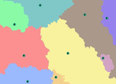
The resulting allocation raster.
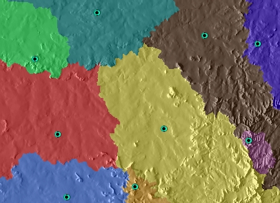
The resulting allocation raster over the Hillshade of the
terrain. Illustrates that the boundaries of the zones allocated to
the Centers are on very steep terrain (slope is big - the cost is high).
Notes:
- Supported raster formats are File Geodatabase raster, Personal Geodatabase
raster and file based raster formats (ESRI GRID, Erdas Imagine and
TIFF).
- For file based rasters initially the name of the output raster
defines the raster format
- no extension specified - ESRI binary GRID
- .img extension (for example raster1.img) -
ERDAS IMAGINE image.
- .tif extension (for example raster1.tif -
Tagged Image File Format (TIFF) image.
- The initial output raster format can be
changed by selecting the desired output in the dialog.
- The input feature class and cost raster must
be in the same projected
coordinate system.
- The result raster can be easily converted to
a polygon feature class using the standard ArcGIS Raster To Polygon tool
- The attributes can be transferred to the
polygons by joining the Raster Attribute Table to the polygons using
GRID_CODE field of the feature class and the Value field of the raster
attribute table.
ToolBox
implementation
Command line syntax
ETS_GPCostAllocationRaster <Input
Points> <Cost Raster> <Out Raster> <ID Field> {Cut Off Cost}
Parameters
| Expression |
Explanation |
| <Input
Points> |
A
Point layer feature class |
| <Cost
Raster> |
A
Raster dataset or Raster layer |
| <Out
Raster> |
A String
- the full name of the output raster (A raster with the same full
name should not exist). The output raster type depends on the extension
of the output file(see Notes above) |
|
<ID Field> |
A String representing the name
of the field in the input point feature class to be used as point ID. |
|
{Cut Off Cost} |
A Double representing the cut
off cost - the value of the cells with larger
than this cost (distance x weight) to reach will be set to NODATA |
Scripting syntax
ETS_GPCostAllocationRaster (Input
Points,
Cost Raster, Out Raster, ID Field, Cut Off Cost)
See the explanations above:
<> - required parameter
{} - optional parameter
.NET implementation
(Go to TOP)
CostAllocationRaster (inFeatureClass As IFeatureClass,
costRasterDataset As IRasterDataset2, sOutRaster As String,
sIDField As String, Optional dCutOff As Double = 0) As IRasterDataset2
| Copyright © Ianko Tchoukanski |