Uses Inverse Distance
Weighted Interpolation (IDW) to interpolate a raster from the input
features.
Inputs:
- A Point or Polyline feature layer or feature
class.
- Output raster name and format
- Cell Size of the output raster
- Value field - a field from the
attribute table to be used as a source for the values of the raster. If the
input is of PointZ or PolylineZ type, the Z values of the features can be
used as source for the raster values
- Power - A positive number that defines the
weight of the distance in the interpolation process. The weight of each
known point decreases as the distance from it to the interpolated cell
increases. The higher the value of the Power, the faster the weight of the
known point decreases. If the Power is less than 1 the appearance of the
resulting surface will be sharper. If the value of the Power is greater than
1 the appearance of the surface will be smoother. Very large values of the
Power will result of a surface with only few known points influencing the
value of the interpolated cell. The most commonly used value is 2 (default)
- Number of sources - the number of known
points to be used in the interpolation of the value of each cell. The
default value is 12.
- Cut off distance (optional) - a known point
will not influence the interpolation of cells that are farther than this
distance from the point.
Output:
Examples:
Power = 0.5
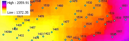
Power = 2
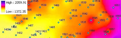
Power = 15

Notes:
- Supported raster formats are File Geodatabase raster, Personal Geodatabase
raster and file based raster formats (ESRI GRID, Erdas Imagine and
TIFF).
- For file based rasters initially the name of the output raster
defines the raster format
- no extension specified - ESRI binary GRID
- .img extension (for example raster1.img) -
ERDAS IMAGINE image.
- .tif extension (for example raster1.tif -
Tagged Image File Format (TIFF) image.
- The initial output raster format can be
changed by selecting the desired output in the dialog.
- The feature class must be in a projected
coordinate system
ToolBox
implementation
Command line syntax
ETS_GPIDW <Input Dataset> <Out Raster> <Elevation Field> <
Cell Size>
<Power> <Number of Sources> {Cutoff Distance}
Parameters
| Expression |
Explanation |
|
<Input Dataset> |
A
Point, Polyline or Polygon layer or feature class |
| <Out
Raster> |
A String
- the full name of the output raster (A raster with the same full
name should not exist). The output raster type depends on the extension
of the output file(see Notes above) |
|
<Elevation Field> |
A String representing the name
of the field which values are going to be used for interpolation. |
|
<Cell Size> |
A Double representing the cell
size of the output raster. |
| <Power> |
A Number - see main
description above |
| <Number
of Sources> |
A Number - see description
above |
| {Cutoff
Distance} |
A Double representing the
Cutoff distance. |
Scripting syntax
ETS_GPIDW (Input Dataset, Out
Raster, Elevation Field, Cell Size, Power, Number of Sources ,Cutoff Distance)
See the explanations above:
<> - required parameter
{} - optional parameter
.NET implementation
(Go to TOP)
IDW (inFeatureClass As IFeatureClass,
sOutRaster As String, sElevationField As String,
dCellSize As Double, dPower As Double, iNumPoints As Integer,
Optional dCutoff As Double = 0) As IRasterDataset2
| Copyright © Ianko Tchoukanski |