Go to ET GeoWizards 12.x User Guide
Polyline To Point
Go to ToolBox
Implementation
Converts a polyline data set to a point feature class
Inputs:
- A polyline feature layer
- Conversion option
- Vertices - the vertices of all polylines will be converted to points. If the
"Remove duplicate points" option is selected the duplicate points created from
the nodes of two polylines sharing a common node will be represented by one point. Note
that if this option is used the attempt to convert back these points to polylines will
produce incorrect result.
- Nodes - only the nodes of each polyline will be exported.
- Middle points - only the middle point of each polyline will be exported.
- More options
- Remove Duplicate Points - the duplicate points created from the
vertices of two adjacent polygons will be represented by one point. Note
that if this option is used the attempt to convert back these points to
polygons will produce incorrect result
- Calculate point Position along boundaries
- If used the [ET_Order] field will be populated with the
relative location of the vertex (0 to 1) from the start of the
polylines.
- If not used, the [ET_Order] field will be populated with the
order of the vertex in the polyline (from 0 to number of vertices)
- Preserve Z(M) available only if the input feature class is of
PolygonZ(M) type. If selected, the result will be of PointZ(M) type,
otherwise the result will be of plain points (no Z or M values)
Outputs:
- New point feature class
- All the original attributes of the
polylines are transferred to the point attribute table
- New fields are added to the point
attribute table
- [ET_ID] - the FID of original polylines. The values can be used to link the points back
to the polylines.
- [ET_IDP] - this is a unique number identifying each
part of the polylines. If a polyline
with FID = 356 has 3 parts, the corresponding points will have values in this fields
356_0, 356_1 and 356_2.
- [ET_X] - the X coordinates of the
resulting points
- [ET_Y] - the Y coordinates of the
resulting points
- If the conversion option is "Vertices" or "Nodes"
an Order field is added
- [ET_Order] - the position of the point along the polyline . The
value can be from 0 to 1 (if the Calculate point Position option is
used) or from 0 to number of vertices (if not). The value of this attribute
can be used if the polyline have to be recreated from these points.
- If the "Assign angle
attribute" option is used an angle field is added
- [ET_Angle] - the angle of the polyline in this point.
Notes :
- See above for the use of the "Remove duplicate points" option
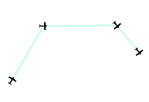
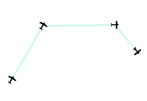
- If the "Assign angle attribute" option is used, the points symbols can be
rotated and in such a way can represent the direction of the polylines. See the example
below
- The functionality of the PolylineZ(M) To Point function available in the
pre 11.0 versions is entirely included in this function.
Example:
Angle at the start of segments |
Angle at the end of segments |
|
|
ToolBox
implementation
(Go to TOP)
Command line syntax
ET_GPPolylineToPoints <input_dataset>
<out_feature class> <Vertex | Middle | Node> {remove_duplicates} {calc_point_pos} {point_angle} {angle_at_start} {keep_ZM}
Parameters
| Part |
Description |
| <input_dataset> |
A
Polyline feature class or feature layer |
|
<out_feature class> |
A String
- the full name of the output feature class (A feature class with the same full
name should not exist) |
| <Vertex
| Middle | Node> |
Convert
Option. A String - the export option to
be used. The available options are (Case
sensitive):
- "Vertex" - - the
vertices of all polylines will be converted to points. If {remove_duplicates}
is True the duplicate points created from the nodes of
two polylines sharing a common node will be represented by one
point.
- "Middle" - only the middle
point of each polyline will be exported.
- "Node" - only the nodes of
each polyline will be exported. If {remove_duplicates} is True
the duplicate points created from the nodes of two polylines sharing
a common node will be represented by one point.
|
| {remove_duplicates} |
A Boolean used only with
Convert Option = "Vertex" and Convert Option
= "Node". If True the duplicate points representing
coincident nodes will be removed.
|
| {calc_point_pos} |
A Boolean indicating whether the
position of the points along the polylines to be calculated (only if the
"Vertex option is used) |
| {point_angle} |
A
Boolean - indicates whether an angle attribute to be added to the point
attribute table. |
| {angle_at_start} |
A
Boolean - indicates from which polyline segment to be calculated the
angle. True - from the start segment, False3 from the segment end. See
the main page of the function for an example. |
| {keep_ZM} |
A Boolean indicating whether the the
output will be of Z(M) type (only if the input dataset is of Z(M) type) |
Scripting syntax
ET_GPPolylineToPoints (input_dataset,
out_feature class, convert_option, remove_duplicates, calc_point_pos,
point_angle, angle_at_start, keep_ZM)
See the explanations above:
<> - required parameter
{} - optional parameter