TRIANGULATED IRREGULAR NETWORK
The TIN model represents a surface as a set of contiguous, non-overlapping triangles. Within each triangle the surface is represented by a plane. The triangles are made from a set of points called mass points.
Mass points can occur at any location, the more carefully selected, the more accurate the model of the surface. Well-placed mass points occur where there is a major change in the shape of the surface, for example, at the peak of a mountain, the floor of a valley, or at the edge (top and bottom) of cliffs.
The TIN model is attractive because of its simplicity and economy and is a significant alternative to the regular raster of the GRID model.
Quick comparison
- TIN
- Advantages:
- Ability to describe the surface at different level of resolution
- Efficiency in storing data
- Disadvantages:
- In many cases require visual inspection and manual control of the network
- Advantages:
- GRID
- Advantages:
- Easy to store and manipulate
- Easy integration with raster databases
- Smoother, more natural appearance of derived terrain features
- Disadvantages:
- Inability to use various grid sizes to reflect areas of different complexity of relief.
- Advantages:
The Delaunay Triangulation
Delaunay triangulation is a proximal method that satisfies the requirement that a circle drawn through the three nodes of a triangle will contain no other node
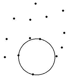
Input Points
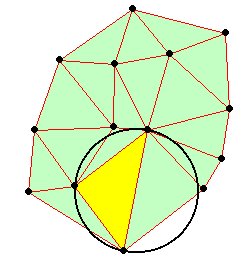
TIN produced
Delaunay triangulation has several advantages over other triangulation methods:
- The triangles are as equi-angular as possible, thus reducing potential numerical precision problems created by long skinny triangles
- Ensures that any point on the surface is as close as possible to a node
- The triangulation is independent of the order the points are processed
TINs from contours
Contours are a common source of digital elevation data. In general all the vertices of the contour lines are used as mass points for triangulation. In many cases this will cause the presence of flat triangles in the surface.
Flat triangles are created whenever a triangle is formed from three nodes with the same elevation value
Flat triangles are frequently generated along contours when the sample points occur along the contour at a distance that is less than the distance between contours. When these "excess" vertices are not removed , the Delaunay triangulation discovers that the closest sample points are those along the same contour, causing the generation of flat triangles.
The flat triangles have a slope of 0 and do not have defined aspect. They might cause problems when the surface is used for modeling.
Example:
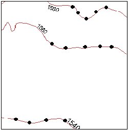
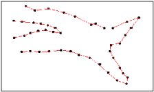
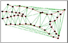
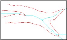
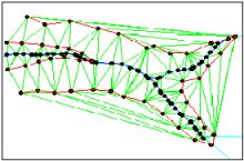
The contours
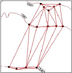
The triangulation - We can see several flat triangles here
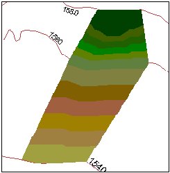
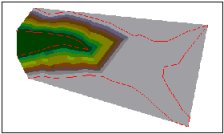
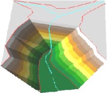
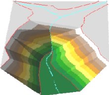
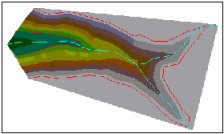
The elevation
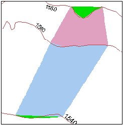
The slope- The green areas indicate Slope = 0 (flat triangles)
How can we avoid the flat triangles?
- By adding more mass points
- Generalizing the contours
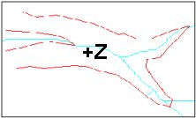
- By adding break lines
Break lines
Linear features which define and control surface behavior in terms of smoothness and continuity are called break lines.
Types break lines:
- Soft break lines are used to ensure that linear features and polygon edges are maintained in the tin surface model by enforcing the break line as tin edges. However, they do not define interruptions in surface smoothness – break lines with no Z value
- Hard break lines define interruptions in surface smoothness – break lines with Z value
Example:
No Breaklines
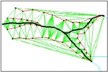
Triangulation
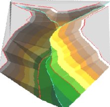
Surface
3D View
Soft Breaklines
Triangulation
Surface

3D View
Hard Breaklines
Triangulation
Surface
3D View
Storing TINs
There are basically two ways of storing triangulated networks:
- Triangle by triangle - better for storing attributes (slope, aspect ..) for each triangle, but uses more storage space.
- Points and their neighbors - better for generating contours and uses less storage space, but slope, aspect , etc must be calculated and stored separately.