Creating contour polygons with attributes from contour polylines.
A contour is a polyline of equal height. By their nature the contours are polyline features, but many GIS users want
to represent the area closed between two adjacent contours with a polygon. If you search GIS forums for Contour Polygons, you will find more than 100
entries. While however creating contour polygons is a comparatively easy task - one just need to build polygons from the contour polylines, the
problem of attaching the contour attributes (Height) to the contour polygons presents some challenges.
What are the major properties of the contour polylines that can be used in order to complete the task:
- In general the contours never intersect. There is an exception in the case where there are overheads in the data, but such a relief phenomenon cannot actually be represented correctly by contours, so we will ignore them in this article.
- A contour polygon is always constructed by two and only two contours. This rule is not valid in two cases:
- On the boundaries of the contour dataset, but the polylines closing the contour polygon on the boundaries are not actually contours, so this should not influence the solution proposed.
- For the highest contours representing ridges, and lowest contours representing depressions.
Only functions available in ET GeoWizards 12.0 are used.
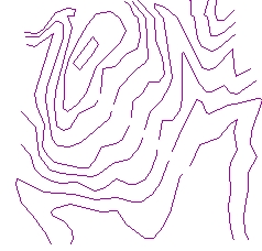
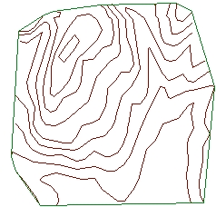
Lets start with a typical contour dataset. Two are the issues we have to consider here:
- The closed contours are easy to handle. How however we handle contours that have gaps? Normally
there are two reasons for the presence of gaps in the contour data:
- Some data captured in CAD systems has gaps left there on purpose, to leave space for labels
- If the contours were captured from separate map sheets and the edge matching between the data from the separate data sheets was not good or not performed at all.
- How to handle the contours that are going out of the study area?
If you are sure that there are no gaps in your contour data, you can skip steps 1 and 2 below.
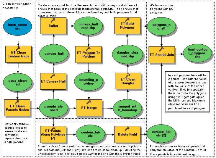
STEP 1: Cleaning gaps in contours. ET GeoWizards has a function called Clean Contour Gaps. It expects the user to provide (apart from the input dataset) two parameters:
- A field representing the elevation value of the contours
- Tolerance - the gaps smaller than this tolerance will be closed.
STEP 2: In the resulting from Step 1 data there are contour polylines that have the same height value - Pseudo Nodes are present. It will be better to have a single polyline for each separate contour. To achieve this we need to get rid of the pseudo nodes - use Clean Pseudo Nodes function of ET GeoWizards
Handling the contours exiting the study area. In order to create polygons representing the contours we have to close the area somehow.
- Manually connecting with a new polyline the dangling nodes of the dataset created in STEP 2. For small datasets this might be the quickest solution, but we very seldom work with such small datasets.
- Creating a bounding rectangle of the dataset and adding it as a polyline to the dataset created in STEP 2
- Creating a Convex Hull of the dataset and adding in to the dataset created in STEP 2.
Depending on the dataset both methods 2. and 3. will automate the process, but most probably both will require some additional data processing to fix the topology errors.
STEP 3: Create Convex Hull of the data - Convex Hull function
STEP 4: Buffer the Convex Hull with a very small distance. This is to ensure that it will not touch the contour polylines which will cause splitting of the original contours during the cleaning process.
STEP 5: Convert the buffered Convex Hull to it's boundary polyline - Polygon To Polyline
STEP 6: Merge the contours created in STEP 2 and the boundary of the buffered Convex Hull created in STEP 5.
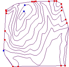
STEP 7: Clean the merged dataset - Clean Dangling Nodes function. Carefully select the dangle tolerance. If needed manually edit some of the contour ends to be as close as possible to the convex hull boundary. Evaluate the result of the function (The Export Nodes function can be used to find out whether there are still dangling nodes present).
Note that an automatic procedure might not be able to fix all topology problems. ET GeoTools offer to users with ArcGIS a large variety of tools that will help you productively analyze and fix topology problems.
Merged contours with convex hull boundary and cleaned - ready for building polygons
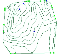
STEP 8: Build polygons from the dataset created in STEP 7 - Build Polygons function.
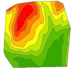
At this stage we have topologically correct polygons representing our original contours. Each polygon is
constructed by its lower and upper contour. Some polygons have edges from the dataset boundary, but we are not interested in these edges
because they do not have any elevation information. The polygons however still do not have any attributes.
How to get the attributes of the contour polyline and populate them to the appropriate polygons?
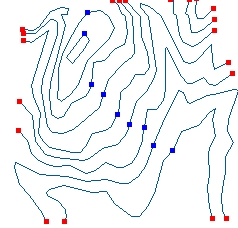
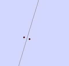
Each contour (see the exceptions above) will have an upper and lower polygon, so if we create two points per
contour polyline - one on the left side and one on the right side very close to the original polyline, one of the points will be in the lower
polygon and the other point in the upper polygon. We will use the contours created in STEP 3 to get the left and right points.
STEP 9: Create Left and Right points - ET Points Along Polylines function if used with "BOTH" option will create two point per polyline one on the left and one on the right side of the polyline, at a relative distance from the start of the polyline (0 to 1) and with a user defined offset from the polyline on the side selected by the user. The points will carry the attributes of the corresponding polylines.
STEP 10: Make sure to preserve in the point dataset only the elevation field. All the other fields can be deleted - use the Delete Multiple Fields function.
As a result of STEP 10 we will have a point dataset. Each point will have the elevation value of the corresponding contour. Each polygon created in STEP 8 will have inside:
- Standard Polygon (between 2 contours) - 2 points with different elevation values (one from the lower and one from the upper contour).
- Ridge and Depression polygons - only one point created from the Lower/Upper contour
- Polygons on the boundary of the original dataset - only one point.
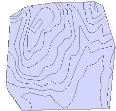
The last step is to transfer the attributes from the points to the polygons.
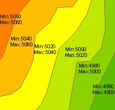
STEP 11: We use Spatial Join with the Many To Many option and tolerance of 0 (we want only the points contained by a polygon to be joined to the polygon) to join the points to the polygons. The function will transfer the attributes of the points to the polygons and will create two new fields - Min and Max elevations (depending on the name of the elevation field in the input dataset.
Notes:
- Since the same relative length (for example 0.5 will give points in the middle of each polyline) is applied for the creation of the LEFT and RIGHT points for all polylines, the location of the points cannot be controlled very well. If the offset distance specified is too large and there are very dense contours some points might not fall in the adjacent polygon, but the next one. Analyze the input data before selecting the offset distance for the points creation.
- Polygons that have only one adjacent contour (top ridges, bottom depressions, on the boundary of the dataset) will have Min Elevation = Max Elevation.
- A polygon for which Abs (Min Elevation - Max Elevation) is greater than the contour interval indicates an error in the process.
- Analyze the output. NEVER accept a result as valid before you have thoroughly checked its correctness.
Sample Model of the entire process (ArcGIS Desktop and ArcGIS Pro only)